This tutorial shows how to display "
Hello World" by Arduino and blink the built-in LED on the Arduino board or blink an external LED via wire connections.
Before working on this example, make sure you understand the pure
Hello World example for Arduino.
Part A. Arduino built-in LED
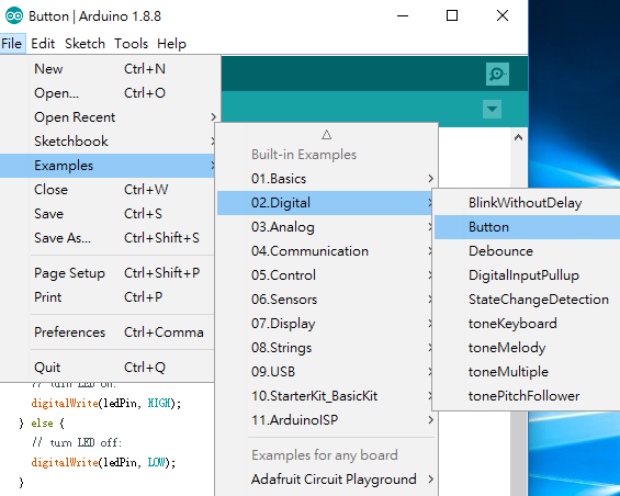
1. Select File->Examples->01.Basics->Blink
2. Modify the code as:
int count=0;
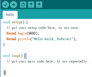
void setup() {
Serial.begin(9600);
// initialize digital pin LED_BUILTIN as an output.
pinMode(LED_BUILTIN, OUTPUT);
}
// the loop function runs over and over again forever
void loop() {
digitalWrite(LED_BUILTIN, HIGH); // turn the LED on (HIGH is the voltage level)
Serial.println("Hello, world!");
delay(1000); // wait for a second
digitalWrite(LED_BUILTIN, LOW); // turn the LED off by making the voltage LOW
Serial.println(count);
delay(1000); // wait for a second
count++;
}
3. Download the code and open the serial monitor
Result:
You should also see the LED on the Arduino board blinking.
Part B. External LED
1. Follow the figure shown in the official page for circuit connections from pin 13 to ground (GND) via an LED. Connect the longer leg / pin of the LED (called the anode) to the pin 13 with 5V power. The resistor value should be between 220 ohm and 1k ohm, but for me 2k ohm also works.
2. Modify the code as below:
int count=0;
int LED13=13; // For the external LED at pin 13
void setup() {
Serial.begin(9600);
// initialize digital pin LED_BUILTIN as an output.
pinMode(LED_BUILTIN, OUTPUT);
pinMode(LED13, OUTPUT);
}
// the loop function runs over and over again forever
void loop() {
digitalWrite(LED_BUILTIN, HIGH); // turn the LED on (HIGH is the voltage level)
digitalWrite(LED13, HIGH); // turn on the external LED at pin 13
Serial.println("Hello, world!");
delay(1000); // wait for a second
digitalWrite(LED_BUILTIN, LOW); // turn the LED off by making the voltage LOW
digitalWrite(LED13, LOW); // turn off the external LED at pin 13
Serial.println(count);
delay(1000); // wait for a second
count++;
}
Result:
Reference:
Arduino: Hello, World! (StudyEECC)