2019/02/16

Adaptive Equalizer 自適應性等化器

在通訊系統中,例如對於電話數據機(modem)的資料傳輸,在低位元率(low bit rate)時,通常比較沒有符號間干擾/符際干擾(Intersymbol Interference, ISI)的問題。

但是當傳輸位元率提高時,例如超過2400 bits時,ISI的問題會變嚴重,這時就需要使用自適應性頻道等化器(Adaptive Channel Equalizer)來克服通道失真(Channel Distortion)的問題。

Adaptive Equalizer當見的實現方式是使用自適應性有限脈衝響應濾波器(Adaptive FIR Filter),其係數採用LMS演算法(Least-Mean-Square Algorithm, 最小均方演算法)進行調整,以克服通道失真。LMS演算法是一種隨機梯度演算法(Stochastic Gradient Algorithm)。

通了使用LMS,Adaptive Equalizer也可採用RLS演算法(Recursive Least-Squares Algorithm, 遞迴最小平方演算法)。

參考資料:

Adaptive equalizer (Wikipedia)
Stochastic gradient descent (Wikipedia) (隨機梯度下降)
Least mean squares filter (Wikipedia) (屬於一種Stochastic Gradient Algorithm)
Recursive least squares filter (Wikipedia)

Haykin, S. S. (2014). Adaptive filter theory. 5th edition, Pearson Education. pp 40-43, 468-471.

Ingle, V. K., & Proakis, G. J. (2014). Essentials of Digital Signal Processing using MATLAB®. CENGAGE Learning, pp 603-606.

2019/01/24

Arduino: Button Detection with LED Control

1. Connect the button circuit according to the official Button page.

2. Connect the LED circuit to pin 13 according to the official Blink page or the circuit in the "Hello World with blinking LED" example.


3. Connect your Arduino to a computer via a USB cable.

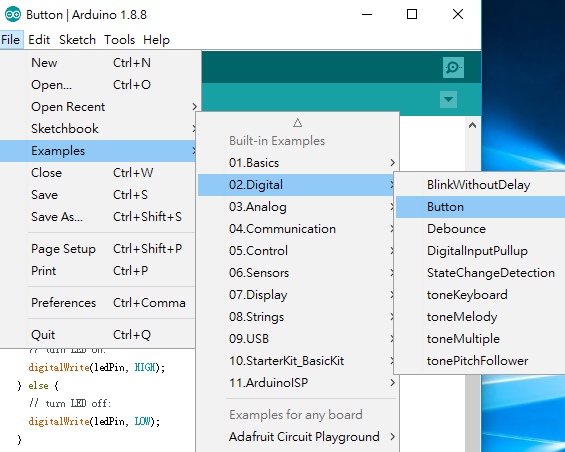
4. Select Example -> 02.Digital -> Button.

5. Download the code. The LED should be turned on by Arduino when the button is pressed.


Related Information:

Arduino: Hello World! (StudyEECC)

2019/01/19

Arduino: Hello World with blinking LED

This tutorial shows how to display "Hello World" by Arduino and blink the built-in LED on the Arduino board or blink an external LED via wire connections.

Before working on this example, make sure you understand the pure Hello World example for Arduino.

Part A. Arduino built-in LED

1. Select File->Examples->01.Basics->Blink

2.  Modify the code as:

int count=0;
void setup() {
  Serial.begin(9600);
  // initialize digital pin LED_BUILTIN as an output.
  pinMode(LED_BUILTIN, OUTPUT);
}

// the loop function runs over and over again forever
void loop() {
  digitalWrite(LED_BUILTIN, HIGH);   // turn the LED on (HIGH is the voltage level)
  Serial.println("Hello, world!");
  delay(1000);                       // wait for a second
  digitalWrite(LED_BUILTIN, LOW);    // turn the LED off by making the voltage LOW
  Serial.println(count);
  delay(1000);                       // wait for a second
  count++;
}

3. Download the code and open the serial monitor

Result:


You should also see the LED on the Arduino board blinking.

Part B. External LED

1. Follow the figure shown in the official page for circuit connections from pin 13 to ground (GND) via an LED. Connect the longer leg / pin of the LED (called the anode) to the pin 13 with 5V power. The resistor value should be between 220 ohm and 1k ohm, but for me 2k ohm also works.

2. Modify the code as below:

int count=0;
int LED13=13; // For the external LED at pin 13
void setup() {
  Serial.begin(9600);
  // initialize digital pin LED_BUILTIN as an output.
  pinMode(LED_BUILTIN, OUTPUT);
  pinMode(LED13, OUTPUT);
}

// the loop function runs over and over again forever
void loop() {
  digitalWrite(LED_BUILTIN, HIGH);   // turn the LED on (HIGH is the voltage level)
  digitalWrite(LED13, HIGH);   // turn on the external LED at pin 13
  Serial.println("Hello, world!");
  delay(1000);                       // wait for a second
  digitalWrite(LED_BUILTIN, LOW);    // turn the LED off by making the voltage LOW
  digitalWrite(LED13, LOW);         // turn off the external LED at pin 13
  Serial.println(count);
  delay(1000);                       // wait for a second
  count++;
}

Result:


Reference:

Arduino: Hello, World! (StudyEECC)

Arduino: Hello, World!

This is the first tutorial with Arduino. "Hello World" is usually the very first program to learn a new programming language with a simple command that prints out the "Hello, World!" message.

2. Connect the Arduino board to your computer via a USB cable. Note that in this case the power of the Arduino board is supplied by the 5V USB cable and it is not required to connect to an external DC adapter.

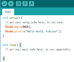
3. In the Arduino IDE window, type the following code:

void setup() {
  // put your setup code here, to run once:
  Serial.begin(9600);
  Serial.println("Hello world, Arduino!");
}

void loop() {
  // put your main code here, to run repeatedly:
}


3. Select Tools -> your Arduino board such as the popular Arduino Uno.

4. Select Tools -> COM port.

5. Select the upload button and save the project.

6. Select Tools -> Serial monitor.

7. You should see the result if the serial monitor is properly set.

Reference:

Hello World
Arduino: Hello World with blinking LED (StudyEECC)

Hello World with TensorFlow

After TensorFlow is installed, you may test the Hello World with commands in Python:

Type python to enter the Python environment:

python

Type the following commands

>>> import tensorflow as tf
>>> hello = tf.constant('Hello, World!')
>>> sess = tf.Session()
>>> sess.run(hello)
b'Hello, World!'
>>> 


Note that b'Hello, World!' represents byte literals.

If you want to print the message in a python file, use this command:

print(sess.run(hello))

Reference:

helloworld.py (GitHub:aymericdamien/TensorFlow-Examples)
What does the 'b' character do in front of a string literal? (Stack Overflow)

2019/01/08

Matlab: FIR comb filter with various zero placement

The following Matlab code tests the effects of different number of zeros and checks the linear phase result.

a = 1;

b1 = [1 -1];

zplane(b1,a);
fvtool(b1,a);
LinPhase1 = islinphase(b1,a) %Check if linear phase

%Notch comb filter
b2 = [1 0 -1]; 
zplane(b2,a);
fvtool(b2,a);
LinPhase2 = islinphase(b2,a) %Check if linear phase

%Notch comb filter
b3 = [1 0 0 -1]; 
zplane(b3,a);
fvtool(b3,a);
LinPhase3 = islinphase(b3,a) %Check if linear phase

%Notch comb filter
b4 = [1 0 0 0 -1];
zplane(b4,a);
fvtool(b4,a);

%Notch comb filter
b5 = [1 0 0 0 0 -1];
zplane(b5,a);
fvtool(b5,a);
LinPhase5 = islinphase(b5,a) %Check if linear phase

Result:

LinPhase1 =

  logical
   1

LinPhase2 =

  logical
   1

LinPhase3 =

  logical
   1

LinPhase5 =

  logical
   1

b1 = [1 -1];


b2 = [1 0 -1]; 


b3 = [1 0 0 -1]; 


b4 = [1 0 0 0 -1]; 

 b5 = [1 0 0 0 -1]; 


2019/01/01

Matlab: IIR Comb Notch or Peak Filter

IIR Comb Notch Filter

fs = 600;
fo = 100;
q = 35;
bw = (fo/(fs/2))/q;
[b,a] = iircomb(fs/fo,bw,'notch'); % Note type flag 'notch'
fvtool(b,a);
zplane(b,a);

Magnitude Response


Phase Response
Pole-Zero Diagram


IIR Comb Peak Filter

Replace the 'notch' string by 'peak':

[b,a] = iircomb(fs/fo,bw,'peak'); % Note type flag 'peak'

Magnitude Response


Phase Response

Pole-Zero Diagram


Reference


iircomb (MathWorks)